Introduction
Hexapod or so-called Stewart platform mechanisms are widely used in precision engineering applications. The big advantage of this mechanism is the parallel linkage of all Degrees Of Freedom (DOF) from the moving platform to the base. In most cases this enables a much stiffer and compact design compared to a conventional mechanism where the independent DOF’s are stacked in a sequential way.
Geometry
The geometry of a generic hexapod system is depicted in the following figure. Index B for ‘Base’ and P for ‘Platform’
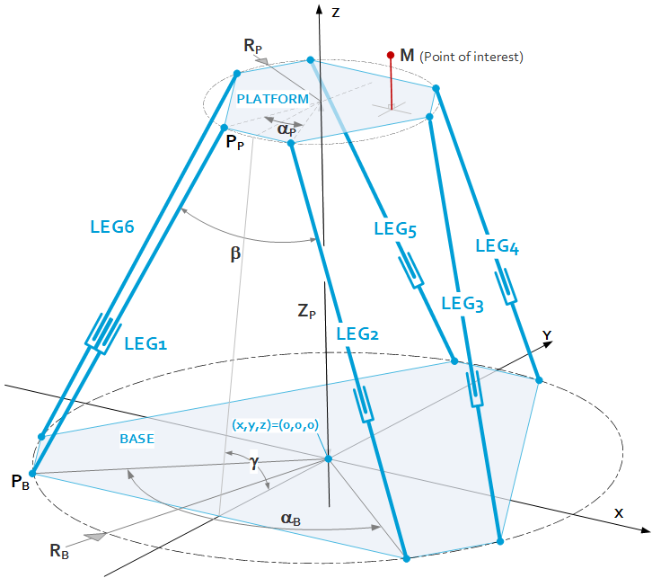
$P_B,\ P_P$
= Hinge locations in the base
$R_B,\ R_P$
= Radius of pitch circle of the hinge locations
$\alpha_{B,\ }\alpha_P$
= Angle between the hinge locations of a leg-pair
$Z_P$
= Z-height of the platform in relation to the base
$M$
= Point of interest of the platform
Kinematics
The kinematics of a hexapod is typically derived via so called inverse kinematics. This means that actuator displacements are derived from platform displacements, and not vice versa. This is related to the fact that a given set of actuator displacements can theoretically correspond to up to 40 platform positions, whereas a given platform position corresponds to a single set of actuator displacements.
The derivation of the inverse kinematics is quite straight forward. First of all, the coordinates of the nominal hinge locations are determined by
$\theta _B=$
$[\begin{matrix}270^{\circ}-\frac{\alpha _B}{2}&270^{\circ}+\frac{\alpha _B} {2}&30^{\circ}-\frac{\alpha _B}{2}&30^{\circ}+\frac{\alpha _B}{2}&150^{\circ}-\frac{\alpha _B}{2}&150^{\circ}+\frac{\alpha _B}{2}\end{matrix}]$
$\theta _P=$
$[\begin{matrix}270^{\circ}-\frac{\alpha _P}{2}&270^{\circ}+\frac{\alpha _P}{2}&30^{\circ}-\frac{\alpha _P}{2}&30^{\circ}+\frac{\alpha _P}{2}&150{}^{\circ}-\frac{\alpha _P}{2}&150^{\circ}+\frac{\alpha _P}{2}\end{matrix}]$
$P_{B_i}=[\begin{matrix}R_B\ {\cdot}\ \cos (\theta _B^{<i>})&R_B\ {\cdot}\ \sin (\theta _B^{<i>})&0\end{matrix}]^T,\ i\in 1..6$
$P_{P_i}=[\begin{matrix}R_P\ {\cdot}\ \cos (\theta _P^{<i>})&R_P\ {\cdot}\ sin (\theta _P^{<i>})&Z_P\end{matrix}]^T,\ i\in 1..6$
When assuming a platform displacement $dM=\left[\begin{matrix}dx&dy&dz&dRx&dRy&dRz\\\end{matrix}\right]^T$ at point of interest $M$ then the displacement of the platform hinge points can be captured by the following formula:
$dP_{P_i}=[\begin{matrix}dx&dy&dz\end{matrix}]^T+[Q(dRx, dRy, dRz)-I_3]\ {\cdot}\ [P_P^{<i>}-M]\ \ i\in 1..6$
With $I_3$ being the 3×3 unity matrix and $Q\left(dRx,dRy,dRz\right)$ the rotation transformation matrix defined as
$Q\left(\theta_x,\theta_y,\theta_z\right)=\left[\begin{matrix}1&0&0\\0&\cos{\left(\theta_x\right)}&-\sin\left(\theta_x\right)\\0&\sin{\left(\theta_x\right)}&\cos(\theta_x)\\\end{matrix}\right]\left[\begin{matrix}\cos{\left(\theta_y\right)}&0&\sin\left(\theta_y\right)\\0&1&0\\-\sin\left(\theta_y\right)&0&\cos{\left(\theta_y\right)}\\\end{matrix}\right]\left[\begin{matrix}\cos{\left(\theta_z\right)}&-\sin{\left(\theta_z\right)}&0\\\sin{\left(\theta_z\right)}&\cos{\left(\theta_z\right)}&0\\0&0&1\\\end{matrix}\right]$
The displaced platform hinge locations are then
$P\Delta_{P_i}=P_{P_i}+dP_{P_i}\ \ i\in 1..6$
And the actuator displacement per leg $s_i$ is then calculated by
$s_i(dM)= \|P{\Delta}_{P_i}(dM)-P_{B_i}\|-\|P_{P_i}-P_{B_i}\|\ \ i\in 1..6$
With this the inverse kinematics matrix $T^{-1}$ can be derived as
$T^{-1}=\left[\begin{matrix}\frac{s_1\left(\left[\begin{matrix}dx\\0\\0\\0\\0\\0\end{matrix}\right]\right)}{dx}&\frac{s_2\left(\left[\begin{matrix}0\\dy\\0\\0\\0\\0\end{matrix}\right]\right)}{dy}&\frac{s_3\left(\left[\begin{matrix}0\\0\\dZ\\0\\0\\0\end{matrix}\right]\right)}{dz}&\frac{s_4\left(\left[\begin{matrix}0\\0\\0\\dRx\\0\\0\end{matrix}\right]\right)}{dRx}&\frac{s_5\left(\left[\begin{matrix}0\\0\\0\\0\\dRy\\0\end{matrix}\right]\right)}{dRy}&\frac{s_6\left(\left[\begin{matrix}0\\0\\0\\0\\0\\dRz\end{matrix}\right]\right)}{dRz}\end{matrix}\right]$
such that the hexapod kinematics can be calculated by
$\vec{s}=T^{-1}\cdot\vec{dM}$
$\vec{dM}=T\cdot\vec{s}$
Note that $\vec{dM}$ contains both translation as well as rotations, which typically imposes the use of dimensionless values referenced to SI units.
Range of motion
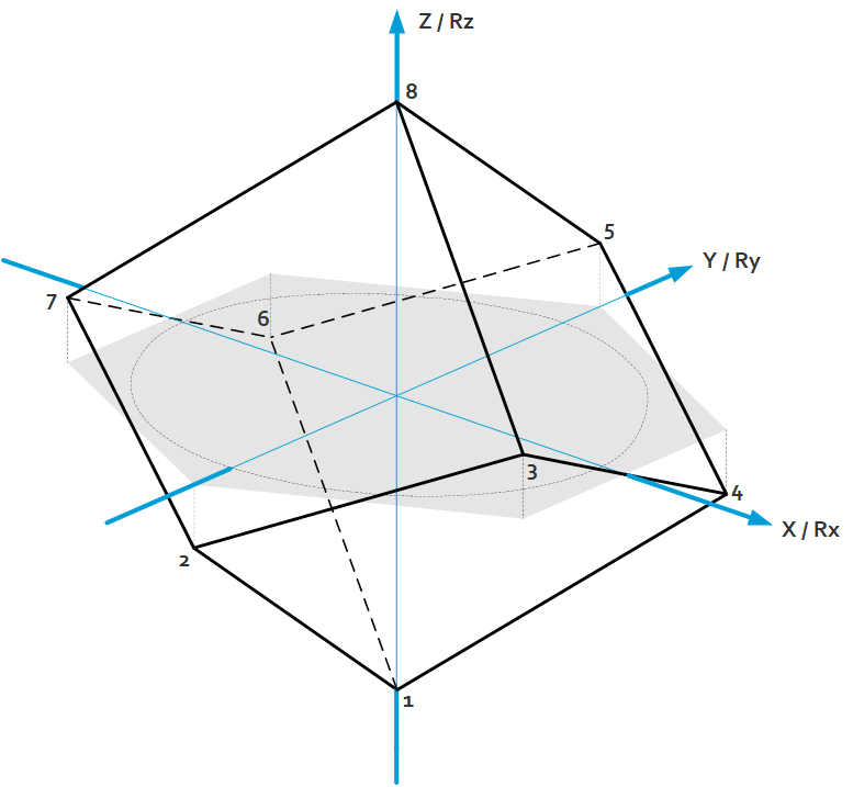
For hexapods the range of motion is difficult to capture as the range in 1 DOF is always dependent on the state of the other DOF’s. Looking to translations or rotations only, then the ranges can be captured by the following cube-like volume spanned by the corner points 1…8.
For a given geometry these corner points can be reconstructed numerically by the fact that the projection of points 2…7 on the XY / RxRy plane is an equilateral hexagon.